31c3 talk and slides
A video recording and the slides from our talk at 31c3 are now available. As always, the congress was a lot of fun - so a big Thank You to everyone involved!
A video recording and the slides from our talk at 31c3 are now available. As always, the congress was a lot of fun - so a big Thank You to everyone involved!
In the video below, you see the first demo of our Acrobot in motion. However, this is work in progress - we cannot balance it at the top yet. Read on for more details.
After the mechanical construction of the Acrobot was finished, we had to develop a suitable motor controller to power the BLDC motor. As mentioned in the last blog post, most R/C BLDC controllers employ sensorless commutation, which leads to jerky motion at startup and for slow speeds and is therefore of little use for us. Thus, we added an encoder to the motor axis and started to develop a new controller. To reduce development effort, we re-used the power stage from a cheap sensorless BLDC controller, but completely replaced the logic by an STM32 microcontroller board. We also added current sensors to be able to precisely measure the current in the motor.
Initially, we used a "standard" BLDC control algorithm with the commutation timing determined by the motor encoder. This, however, still resulted in fairly jerky motion at low speeds. Therefore, we implemented space vector modulation, i.e. we feed the motor with actual 3-phase AC current, the phase of which is locked to the motor motion via the encoder. The new controller works fairly well, but still requires some cleanup. It will be documented in detail in a future blog post.
Now that the Acrobot hardware works, it is time to work on the control algorithms. For the demo in the video above, we used a very simple energy-pumping controller, as suggested in a paper by M. Spong. The idea is to use a PD controller to control the angle of the active joint, \(q_2\), and dynamically set it to
where \(\alpha\) is a fixed parameter (gain) and \(\dot{q}_1\) is the angular velocity of the passive joint. Obviously, this needs an initial "kick" to get started, so we manually play with the offset in the beginning. If the gain is adjusted correctly, we can pump enough energy into the system such that the Acrobot almost gets to the top, but does not swing over. As we cannot capture it yet, we simply switch off the controller after a while and let the system swing down again.
The next step will be to implement more sophisticated control schemes to actually capture the Acrobot at the top and balance it there. After that, we need to clean up, document, and release everything.
A video recording and the slides from our EHSM talk are now available. Many thanks to the EHSM team for the invitation and the video team at DESY for the recording!
We will be giving a talk at this year's Exceptionally Hard & Soft Meeting (EHSM).
In the talk, we will present the physics of walking and how a successful walking machine can be built, at least in simulation. We will then discuss our plans for moving from simulation to actual hardware.
We also plan to bring the Acrobot, hopefully finished by then.
See you there!
The Cartwheel 3D framework by S. Coros et al. is one of the few physics-based controllers for humanoid characters with freely available source code (Apache 2.0). This fact made it a good starting point for our own research into humanoid motion. However, the focus of the Cartwheel project is on being a tool for animation, rather than on controlling actual robots.
We have tried to make a minimal version of the Cartwheel framework. In particular, we have tried to cleanly decouple the controller from the physics engine. The controller gets the full state of the robot and outputs joint torques, the physics simulation uses these to step forward in time and provide the controller with the new robot state. This will allow us to experiment with different physics engines, easily add sensor or motor noise, or run the controller within frameworks like Gazebo.
Another change we made to the controller is the way the maximum virtual force on the root is calculated. The original controller would reduce the force once the foot started lifting of the ground, which we found to be a source of chatter (i.e. torque spikes). We have replaced this by a calculation based on the center-of-pressure concept, which always limits the force to a safe values. This significantly reduced the torque spikes. In addition, it allows us to run the controller in "magnetic boots" mode, which is very useful for debugging.
The video above shows the walk cycle generated by our version of the Cartwheel controller. The simulated robot weighs 47 kg, with each leg contributing 8.1 kg. In the figures below, joint angles, velocities, torques and power are shown (for one step). The dashed lines mark the times when the stance foot switches. Data is shown for the left foot, which is first the swing foot and then the stance foot.


As per the goal of the original authors, the motion looks very natural. There are, however, a number of issues:
The torque curves still contain spikes and other high-frequency content. Trying to clip or low-pass filter the motor torque causes the controller to fail. Since an actual motor controller would likely not have the required bandwidth (nor would that be desirable), the controller as-is cannot be used on a physical robot.
The controller wastes energy by speeding up the robots center of gravity during one half of a step, then slowing it down again during the next half.
The swing leg is not fully extended when it makes contact with the ground.
The controller uses the next foot position as a way to control the center of mass velocity. While this is a legimitate and powerful concept, it is rather hard to accommodate additional requirements, e.g. from trying to walk on ground that is not perfectly flat.
We will try to address these issues in our next-generation controller, which is currently being researched.

Deckel FP2 milling machine
Ever since the inception of the eXperimental Robot Project, it was clear that the project would require at least somewhat professional metalworking equipment. In particular, a milling machine always was very high on our wish list.
It was therefore a very nice surprise when, in summer 2013, the Dingfabrik got an old deckel FP2 milling machine as a donation. Despite being built in 1968, these machines are still in use in professional workshops. While it is a conventional milling machine (no CNC), ours was upgraded with digital scales on all axes, which makes manual milling much easier.
Since the machine weighs around 1000 kg, actually using it had to wait until we moved to our new location. The new location is in a backyard cellar, so the first step was to bring the (disassembled) machine into the backyard and then down into the cellar through a ceiling light. This work took place on what was probably the hottest weekend in that summer.
After arriving, the machine was carefully packaged in plastic to avoid getting dust on it during the renovation of the new rooms.
Finally, in spring 2014, everything was ready and we could unwarp our new present! The first task was to repaint parts of the machine, then assemble it.
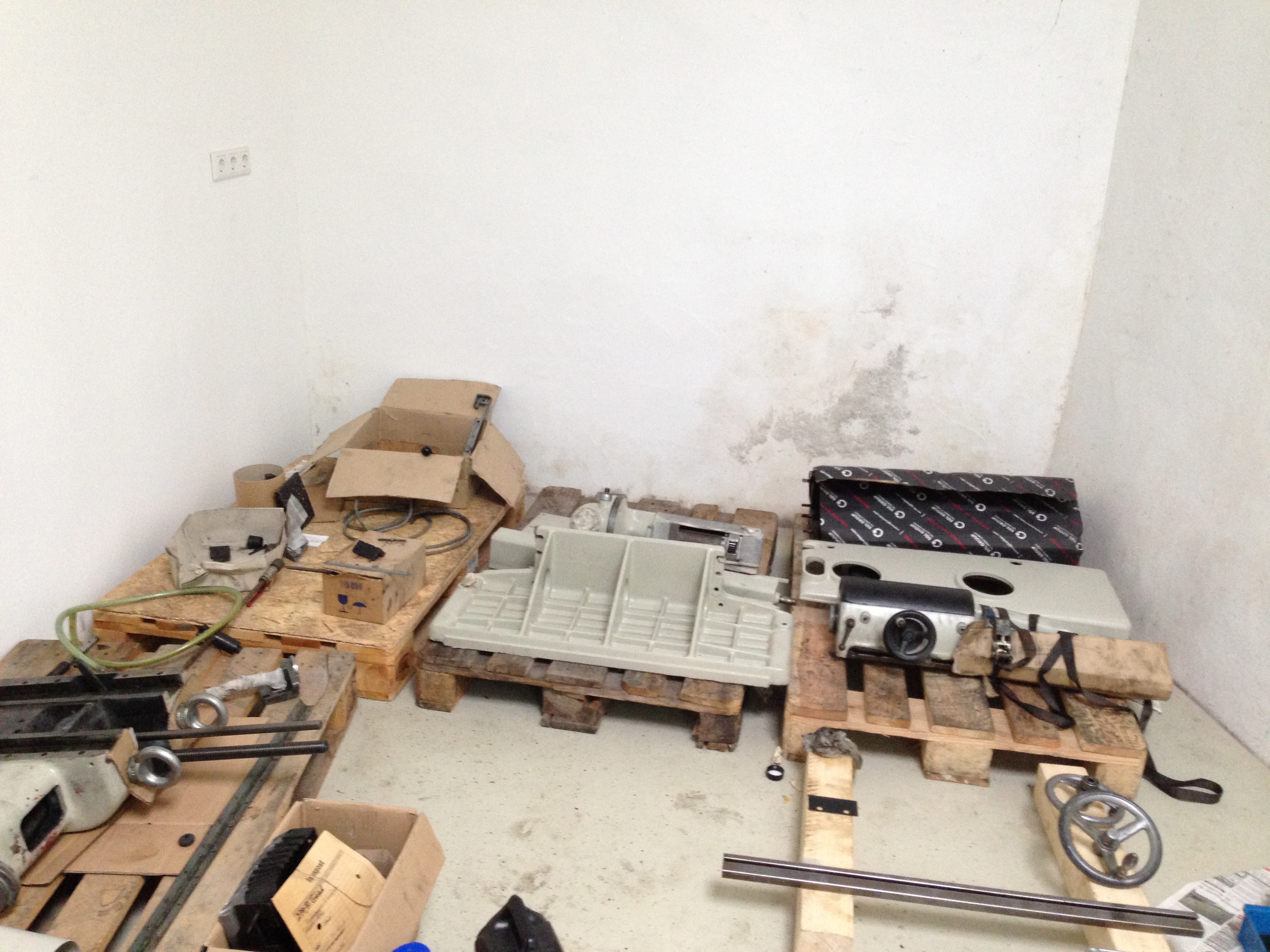
Most of the part still laying on the pallets they came on
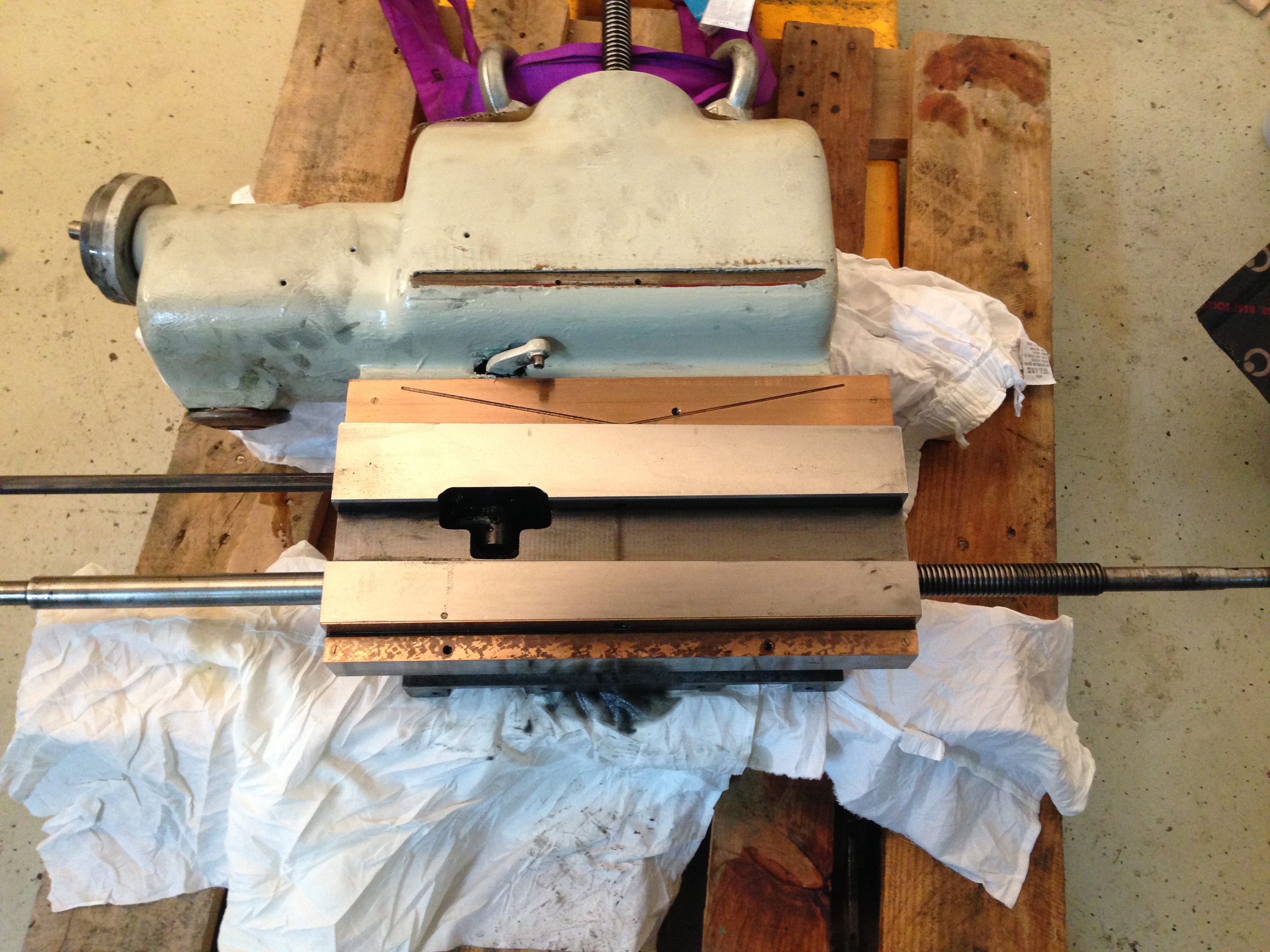
Cleaned X-Y Carriage on palette
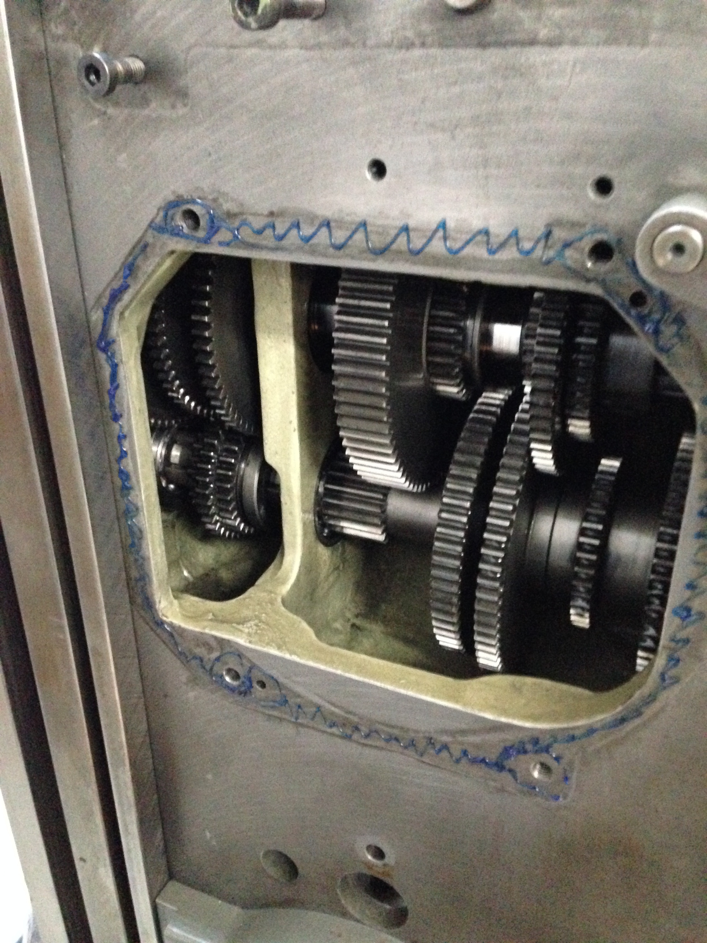
Gearbox for adjusting the spindle speed

Deckel FP2 milling machine
Since we still do not have three-phase power at the new location, a Huanyang Inverter variable frequency drive was acquired to drive the motor. This allowed us to perform first tests with the machine. Up to now we are pretty confident that the machine will match all our initial requirements.
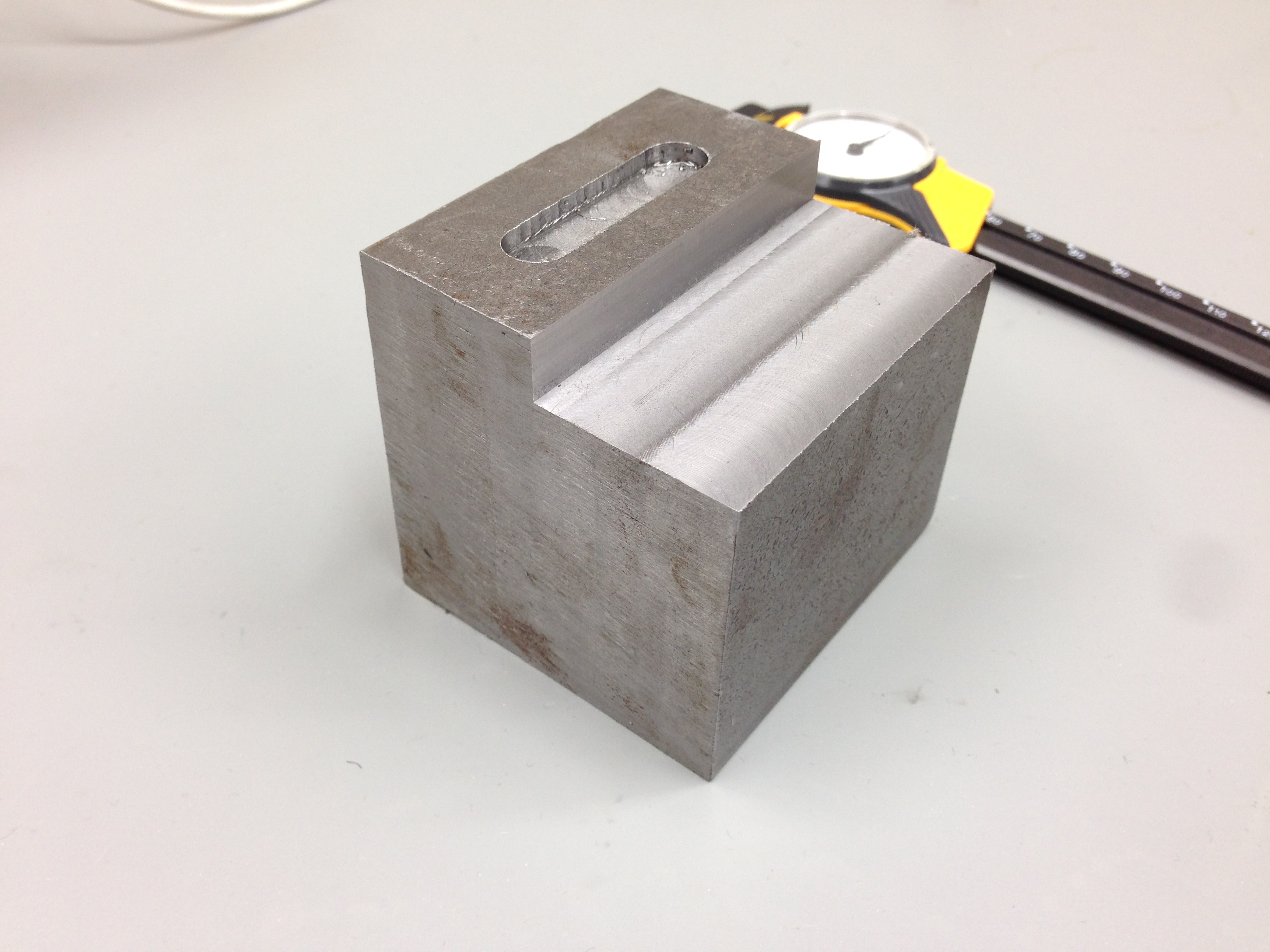
First milling tests
We are currently waiting for the last spare parts, a complete set of way wipers, to arrive. As a first project, we will then produce all custom parts for the Acrobot.
In order to gain experience with a smaller, less ambitious project, we decided to build an Acrobot.
The Acrobot is a famous toy system in optimization based control. It consists of a double pendulum where only the middle joint is actuated. The task for the controller is to drive the Acrobot from its rest position (hanging down) to the goal position, pointing straight up.
We use the open-source PSOPT code to generate trajectories for the Acrobot. This is mostly a black-box method, i.e. it does not require any specific knowledge about the Acrobot. You just supply it with the equations of motion, the start and goal configurations and an objective that allows it to choose between the (infinitely many) possible trajectories. Like all non-linear optimization, it required a bit of fiddling to get it to work, but in the end, the process was relatively painless.
Our Acrobot will use an R/C BLDC motor, which drives the middle joint through a timing belt, providing a 1:5 reduction. The simulation suggests that this motor should have ample torque and velocity reserves for the task.
One problem with R/C BLDC controllers is that they usually employ sensorless commutation. This avoids needing an encoder on the motor shaft. However, sensorless commutation only works when the motor is already turning. Starting is a bit of a black art and never perfect, causing jaggy motion during startup. This is of no use for the Acrobot project, where precisely tracking trajectories is essential. We have therefore build a sensor-based BLDC controller, which will be the subject of future blog posts.
The video above shows a model of the Acrobot, generated from actual CAD drawings, executing the trajectory PSOPT calculated for it.
Of course, actually executing the trajectory requires some form of feedback to correct the tracking errors that inevitably occur. We plan to use the LTV-LQR method for this, which will be discussed in the next post in the series.
Actual construction will start once our mill is ready, probably in 1 to 2 weeks. You can find the current version of the construction drawings in the acrobot-hardware repository.
Welcome!
This is the blog of the eXperimental Robot Project, a project that attempts to build an open hardware humanoid robot - or, more precisely, a bipedal walking machine.
We are two robot enthusiasts from Cologne, Germany. For some years, we have been dreaming about building our own humanoid robot. However, finding plans for one has proved to be rather hard. The most impressive robot projects are very secretive, often not publishing anything beyond videos of their robots in action. University projects are more open; one can often find detailed descriptions of the mechanical construction or the control algorithms (e.g. Lola or TUlip). Still, it is very rare to find source code or CAD files, much less under an open license. The only open-hardware humanoid that we know about is the iCub, but that robot does not seem to be able to walk.
Another issue is cost. The iCub robot costs 250,000€ to build. Rumour has it that Asimo costs 150,000$ to lease for one month (reliable numbers seem hard to come by). Generally, many robots seem to be built in such a way that the cost for components alone is far beyond our budget.
This blog will document our efforts to make our dream come true. We will attempt to bring down the cost by about two orders of magnitude, to design a robot that can be built for a few thousand Euros. All hard- and software will be available under an open license for everyone to study, copy and improve. In addition, we will openly publish our ideas, findings, but also our failures.
The project has been brewing for some time now. We started by studying the problem of walking in simulation - details will follow in future blog posts. Such simulations can give us an idea about the requirements for our hardware, but, of course, they always happen in an idealized world. At some point, only trail and error in the real world will tell us what works and what does not.
Thus, we needed to set up a lab. In summer 2013, Dingfabrik, the local hackerspace where we are located, moved into a new location. As always, moving is a lot of work, and it kept all members busy for several months. In the end, however, it was worth it: we now have a lot of space, including a room dedicated to our robot project, and a reasonably complete electronics and mechanics workshop.
We decided to start with a less ambitious project, a so-called Acrobot (see next blog post). At this time, construction drawings and the control concept are mostly finished, so actual construction can start.
While our project is still rather young, we have decided that now is a good time to making it public - in the spirit of "release early, release often". We hope that others may find it interesting, contribute ideas or code, or even join the project. If you are interested, please get in touch.
That's it with the introduction - in the next blog posts, we will start talking about technical details. Welcome abord an exciting journey!